

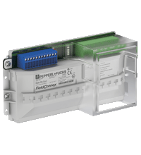
FieldBarrier® RD0-FB-Ex4.*
- 4 outputs Ex ia IIC
- FieldBarrier in Zone 1/Div. 2
- Instruments in Zone 0...1/Div. 1
- Short circuit current limitation per output
- For FOUNDATION Fieldbus H1 and PROFIBUS PA
- Power, Com, and Error LEDs
- Supports FISCO and Entity
- Integrated cable tie-downs
- Supports all grounding methods


Please note: All product-related documents, such as certificates, declarations of conformity, etc., which were issued prior to the conversion under the name Pepperl+Fuchs GmbH or Pepperl+Fuchs AG, also apply to Pepperl+Fuchs SE.
Download the complete datasheet as a PDF:
Datasheet excerpt: Technical data of RD0-FB-Ex4.*
| General specifications | ||
|---|---|---|
| Design / Mounting | Cabinet installation | |
| Fieldbus connection | ||
| Main cable (Trunk) | ||
| Connection | input (Trunk IN): terminals 3+, 4-, 5s output (Trunk OUT): terminals 7-, 8+, 6s |
|
| Rated voltage | 32 ... 16 V DC | |
| Rated current | 31 mA ... 26 mA (without load) 77 mA ... 115 mA (at 20 mA load per input) 120 mA ... 209 mA (at 40 mA load per input) 135 mA ... 241 mA (short-circuit on all outputs) |
|
| Voltage drop | trunk IN to trunk OUT 100 mV max. | |
| Number of couplers | max. 4 per segment | |
| Outputs | ||
| Number of devices per output | 1 | |
| Connection | output 1: terminals 10+, 11-, 12S shield; output 2: terminals 13+, 14-, 15S shield; output 3: terminals 16+, 17-, 18S shield; output 4: terminals 19+, 20-, 21S shield |
|
| Rated voltage | 10 ... 13 V | |
| Rated current | max. 43 mA | |
| Short-circuit current | 50 mA | |
| Indicators/operating means | ||
| LED voltage Fieldbus | green: on, bus voltage existent | |
| LED status output | red flashing: short-circuit | |
| Galvanic isolation | ||
| Main wire/outputs | isolation is not affected by interference according to EN 50020, voltage peak value 375 V | |
| Directive conformity | ||
| Electromagnetic compatibility | ||
| Directive 2014/30/EU | EN 61326-1:2013 | |
| Standard conformity | ||
| Electromagnetic compatibility | NE 21:2006 | |
| Degree of protection | IEC/EN 60529 | |
| Fieldbus standard | IEC 61158-2 | |
| Climatic conditions | DIN IEC 721 | |
| Corrosion resistance | acc. to ISA-S71.04-1985, severity level G3 | |
| Ambient conditions | ||
| Ambient temperature | -50 ... 70 °C (-58 ... 158 °F) | |
| Storage temperature | -40 ... 85 °C (-40 ... 185 °F) | |
| Mechanical specifications | ||
| Connection type | fixed terminals, plug-in terminals | |
| Core cross section | up to 2.5 mm2 | |
| Housing | see figure 1 | |
| Housing material | Polycarbonate | |
| R... DIN rail housing | PA 6.6 | |
| Degree of protection | IP20 | |
| Mass | 1050 g | |
| Mounting | mounting on DIN rail in cabinet | |
| Data for application in connection with hazardous areas | ||
| EU-type examination certificate | PTB 02 ATEX 2086 | |
| Marking |  II 2 (1) G Ex eb mb [ia Ga] IIC T4 Gb , II (1) D [Ex ia Da] IIIC II 2 (1) G Ex eb mb [ia Ga] IIC T4 Gb , II (1) D [Ex ia Da] IIIC |
|
| Main cable (Trunk) | ||
| Maximum safe voltage | 253 V AC | |
| Outputs | ||
| Power | 975 mW | |
| Voltage | 15.75 V | |
| Current | 248 mA | |
| Directive conformity | ||
| Directive 2014/34/EU | EN IEC 60079-0:2018+AC:2020 , EN 60079-7:2015+A1:2018 , EN 60079-11:2012 , EN 60079-18:2015+A1:2017 | |
| International approvals | ||
| FM approval | CoC 3015728 | |
| Control drawing | 116-0266 | |
| Approved for | Class I, Division 2, Groups A, B, C, D / Class I, Zone 2, AEx nA [ia] IIC T4 | |
| CSA approval | CoC 1845315 | |
| Control drawing | 116-0266 | |
| Approved for | Class I, Division 2, Groups A, B, C, D / Class I, Zone 2, Ex nA [ia] IIC T4 | |
| IECEx approval | IECEx PTB 03.0003 | |
| Approved for | Ex eb mb [ia Ga] IIC T4 Gb , [Ex ia Da] IIIC | |
| Certificates and approvals | ||
| FOUNDATION Fieldbus | FF-846 | |
| Marine approval | DNV A-14038 | |
| General information | ||
| Supplementary information | EC-Type Examination Certificate, Statement of Conformity, Declaration of Conformity, Attestation of Conformity and instructions have to be observed where applicable. For information see www.pepperl-fuchs.com. | |
Classifications
| System | Classcode |
|---|---|
| ECLASS 13.0 | 27242605 |
| ECLASS 12.0 | 27242605 |
| ECLASS 11.0 | 27242605 |
| ECLASS 10.0.1 | 27242605 |
| ECLASS 9.0 | 27242605 |
| ECLASS 8.0 | 27242605 |
| ECLASS 5.1 | 27242605 |
| ETIM 9.0 | EC001601 |
| ETIM 8.0 | EC001601 |
| ETIM 7.0 | EC001601 |
| ETIM 6.0 | EC001601 |
| ETIM 5.0 | EC001604 |
| UNSPSC 12.1 | 39121008 |
Details: RD0-FB-Ex4.*
Function
The FieldBarrier, a device coupler for DIN rail mounting, connects 4 instruments with intrinsic safety (Ex ia/Ex ib) and short circuit current limitation at each output. This ensures proper operation of the segment during faults or hot work at the spur.
High power on the trunk enables maximum cable lengths and device count in any hazardous area. The integrated fieldbus terminator features high-availability design and is selectable.
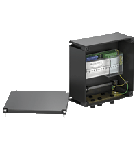
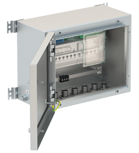
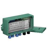
Output terminals with a choice of fixed or plug-in screw terminals connect 1 device each. LEDs simplify troubleshooting and help decrease repair time. Any grounding and shielding concept is possible based on FieldConnex ® enclosure solutions.
Informative Literature: RD0-FB-Ex4.*
| Literature | Language | File Type | File Size |
|---|---|---|---|
| Application Report - Controlling and Monitoring liquid Helium at the Deutsches Elektronen-Synchrotron | ENG | 361 KB | |
| Application Report - Digital Communication in Steel-Plate Manufacturing | ENG | 470 KB |
Product Documentation: RD0-FB-Ex4.*
| Safety and Security Documentation | Language | File Type | File Size |
|---|---|---|---|
| Instruction manual | ENG | 238 KB | |
| Manuals | |||
| Manual | ENG | 787 KB | |
Approvals: RD0-FB-Ex4.*
| Certificates | Cert No. | Language | File Type | File Size |
|---|---|---|---|---|
| Brasil TUV Rheinland Brazil | TÜV 13.1142 | ALL | 1391 KB | |
| Canada CSA | CoC 1845315 | ALL | 45 KB | |
| China SITIIAS CCC Ex Certificate | 2020322316002484 (Singapore) | ALL | 1215 KB | |
| DNV Marine | TAA0000272 | ALL | 100 KB | |
| Europe PTB ATEX Category (1) 2 G | PTB 02 ATEX 2086 | ALL | 3447 KB | |
| PTB IECEx Certificate of Conformity | IECEx PTB 03.0003 | ALL | LINK | --- |
| South Africa MASC | MASC S/18-2697 | ALL | 526 KB | |
| USA FM | CoC 3015728 | ALL | 48 KB | |
| Worldwide Fieldbus Foundation | DC084400 | ALL | 56 KB | |
| Control Drawings | ||||
| Control drawing CSA / Control drawing CSA | ALL | 113 KB | ||
| Declaration of Conformity | ||||
| EU Declaration of Conformity (P+F) / EU-Konformitäterklärung (P+F) | DOC-0810J | ALL | 1133 KB | |
Associated Products: RD0-FB-Ex4.*
| Matching System Components | ||||||
|---|---|---|---|---|---|---|
|
||||||
|
||||||
|
||||||


Pepperl+Fuchs (Aust) Pty Ltd
131-149 Link Drive
Campbellfield, Victoria
Melbourne, Victoria 3061
Australia
sales@au.pepperl-fuchs.com
 +61 3 9358 3400
Pepperl+Fuchs is a leading developer and manufacturer of electronic sensors and components for the global automation market. Continuous innovation, enduring quality, and steady growth have been the foundation of our success for more than 70 years. Pepperl+Fuchs employs 6,300 people worldwide and has manufacturing facilities in Germany, USA, Singapore, Hungary, Indonesia and Vietnam, most of them ISO 9001 certified.