

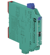
SMART Current Driver KCD2-SCD-Ex1.HC
- 1-channel isolated barrier
- 24 V DC supply (Power Rail)
- Current output up to 625 Ω load
- HART I/P and valve positioner
- Lead breakage monitoring
- Suitable for long field cables (> 1000 m)
- Terminal blocks with test sockets
- Up to SIL 2 acc. to IEC 61508


Please note: All product-related documents, such as certificates, declarations of conformity, etc., which were issued prior to the conversion under the name Pepperl+Fuchs GmbH or Pepperl+Fuchs AG, also apply to Pepperl+Fuchs SE.
Download the complete datasheet as a PDF:
Datasheet excerpt: Technical data of KCD2-SCD-Ex1.HC
| General specifications | ||
|---|---|---|
| Signal type | Analog output | |
| Functional safety related parameters | ||
| Safety Integrity Level (SIL) | SIL 2 | |
| Supply | ||
| Connection | Power Rail or terminals 9+, 10- | |
| Rated voltage | 19 ... 30 V DC | |
| Ripple | ≤ 10 % | |
| Rated current | ≤ 35 mA | |
| Power dissipation | ≤ 600 mW | |
| Power consumption | ≤ 700 mW | |
| Input | ||
| Connection side | control side | |
| Connection | terminals 5-, 6+ | |
| Input signal | 4 ... 20 mA , limited to approx. 27 mA | |
| Input voltage | depending on switch configuration open loop voltage of the control system < 19 V open loop voltage of the control system < 26 V |
|
| Voltage drop | depending on switch configuration open loop voltage of the control system < 19 V: approx. 5 V at 20 mA open loop voltage of the control system < 26 V: approx. 12 V at 20 mA |
|
| Input resistance | > 100 kΩ, with field wiring open | |
| Output | ||
| Connection side | field side | |
| Connection | terminals 1+, 2- | |
| Voltage | ≥ 12.5 V at 20 mA | |
| Current | 4 ... 20 mA | |
| Load | 0 ... 625 Ω | |
| Ripple | 20 mV rms | |
| Transfer characteristics | ||
| Deviation | at 20 °C (68 °F), 0/4 ... 20 mA ≤ ± 0.1 % incl. non-linearity and hysteresis |
|
| Influence of ambient temperature | < 2 µA/K (0 ... 60 °C (32 ... 140 °F)); < 4 µA/K (-20 ... 0 °C (-4 ... 32 °F)) | |
| Frequency range | field side into the control side: bandwidth with 0.5 Vpp signal 0 ... 3 kHz (-3 dB) control side into the field side: bandwidth with 1 mApp signal 0 ... 3 kHz (-3 dB) |
|
| Rise time | 10 to 90 % ≤ 100 ms | |
| Galvanic isolation | ||
| Input/Output | safe electrical isolation acc. to IEC/EN 60079-11, voltage peak value 375 V | |
| Input/power supply | functional insulation acc. to IEC 62103, rated insulation voltage 50 Veff | |
| Output/power supply | safe electrical isolation acc. to IEC/EN 60079-11, voltage peak value 375 V | |
| Indicators/settings | ||
| Display elements | LED | |
| Control elements | DIP switch | |
| Configuration | via DIP switches | |
| Labeling | space for labeling at the front | |
| Directive conformity | ||
| Electromagnetic compatibility | ||
| Directive 2014/30/EU | EN 61326-1:2013 (industrial locations) | |
| Conformity | ||
| Electromagnetic compatibility | NE 21:2006 | |
| Degree of protection | IEC 60529:2001 | |
| Ambient conditions | ||
| Ambient temperature | -20 ... 60 °C (-4 ... 140 °F) | |
| Mechanical specifications | ||
| Degree of protection | IP20 | |
| Connection | screw terminals | |
| Mass | approx. 100 g | |
| Dimensions | 12.5 x 114 x 124 mm (0.5 x 4.5 x 4.9 inch) , housing type A2 | |
| Height | 124 mm | |
| Width | 12.5 mm | |
| Length | 114 mm | |
| Mounting | on 35 mm DIN mounting rail acc. to EN 60715:2001 | |
| Data for application in connection with hazardous areas | ||
| EU-type examination certificate | CESI 11 ATEX 094 | |
| Marking |  II (1)G [Ex ia Ga] IIC , II (1) D [Ex ia Da] IIIC , I (M1) [Ex ia Ma] I II (1)G [Ex ia Ga] IIC , II (1) D [Ex ia Da] IIIC , I (M1) [Ex ia Ma] I |
|
| Output | Ex ia IIC, Ex iaD | |
| Supply | ||
| Maximum safe voltage | 250 V AC (Attention! Um is no rated voltage.) | |
| Equipment | terminals 1+, 2- | |
| Voltage | 20 V | |
| Current | 100 mA | |
| Power | 500 mW | |
| Internal capacitance | 5.7 nF | |
| Internal inductance | negligible | |
| Certificate | PF 11 CERT 1968X | |
| Marking | II 3G Ex nA IIC T4 Gc |
|
| Directive conformity | ||
| Directive 2014/34/EU | EN 60079-0:2012+A11:2013 , EN 60079-11:2012 , EN 60079-15:2010 | |
| International approvals | ||
| UL approval | ||
| Control drawing | 116-0395 (cULus) | |
| IECEx approval | IECEx CES 12.0004 | |
| Approved for | [Ex ia Ga] IIC , [Ex ia Da] IIIC , [Ex ia Ma] I | |
| General information | ||
| Supplementary information | Observe the certificates, declarations of conformity, instruction manuals, and manuals where applicable. For information see www.pepperl-fuchs.com. | |
| Accessories | ||
| Optional accessories | - power feed module KFD2-EB2(.R4A.B)(.SP) - universal power rail UPR-03(-M)(-S) - profile rail K-DUCT-BU(-UPR-03) |
|
Classifications
| System | Classcode |
|---|---|
| ECLASS 13.0 | 27210120 |
| ECLASS 12.0 | 27210120 |
| ECLASS 11.0 | 27210120 |
| ECLASS 10.0.1 | 27210120 |
| ECLASS 9.0 | 27210120 |
| ECLASS 8.0 | 27210120 |
| ECLASS 5.1 | 27210120 |
| ETIM 9.0 | EC002653 |
| ETIM 8.0 | EC002653 |
| ETIM 7.0 | EC002653 |
| ETIM 6.0 | EC002653 |
| ETIM 5.0 | EC001485 |
| UNSPSC 12.1 | 32101514 |
Details: KCD2-SCD-Ex1.HC
Function
This isolated barrier is used for intrinsic safety applications.
It repeats the input signal from a control system to drive HART I/P converters, valve actuators, and displays located in a hazardous area.
Bi-directional communication is supported for HART devices.
An open field circuit presents a high impedance to the control side to allow alarm conditions to be monitored by control systems.
Test sockets for the connection of HART communicators are integrated into the terminals of the device.
Product Documentation: KCD2-SCD-Ex1.HC
| Safety and Security Documentation | Language | File Type | File Size |
|---|---|---|---|
| Instruction manual | ENG | 50 KB | |
| Safety Manual | ENG | 374 KB | |
| Manuals | |||
| Manual | ENG | 3685 KB | |
Design / Simulation: KCD2-SCD-Ex1.HC
| CAD | Language | File Type | File Size |
|---|---|---|---|
| CAD 2-D / CAD 2-D | ALL | ZIP | 458 KB |
| CAD 3-D / CAD 3-D | ALL | STP | 179 KB |
Approvals: KCD2-SCD-Ex1.HC
| Certificates | Cert No. | Language | File Type | File Size |
|---|---|---|---|---|
| CESI IECEx Certificate of Conformity | IECEx CES 12.0004 | ALL | LINK | --- |
| Canada UL cUL | E106378 cUL (QUZW7) | ALL | LINK | --- |
| Canada UL cUL | E106378 cUL (QVAJ7) | ALL | LINK | --- |
| TÜV SÜD Functional Safety Assessment Summary | R-IS-220229-01-REV.1-EX-SUM | ALL | 68 KB | |
| USA UL | E106378 UL (QUZW) | ALL | LINK | --- |
| USA UL | E106378 UL (QVAJ) | ALL | LINK | --- |
| Control Drawings | ||||
| Control drawing UL / Control drawing UL | ALL | 149 KB | ||
Associated Products: KCD2-SCD-Ex1.HC
| Accessories | ||||||
|---|---|---|---|---|---|---|
|
||||||
|
||||||
|
||||||
|
||||||
|
||||||
|
||||||
|
||||||
|
||||||
|
||||||


Choose from various selection criteria like safety integrity level, performance level, device function, and signal type and find the SIL/PL assessed device that you are looking for.


Pepperl+Fuchs (Aust) Pty Ltd
131-149 Link Drive
Campbellfield, Victoria
Melbourne, Victoria 3061
Australia
sales@au.pepperl-fuchs.com
 +61 3 9358 3400
Pepperl+Fuchs is a leading developer and manufacturer of electronic sensors and components for the global automation market. Continuous innovation, enduring quality, and steady growth have been the foundation of our success for more than 70 years. Pepperl+Fuchs employs 6,300 people worldwide and has manufacturing facilities in Germany, USA, Singapore, Hungary, Indonesia and Vietnam, most of them ISO 9001 certified.